
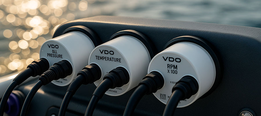
When you’re setting up VDO gauges, you’re not just connecting wires — you’re creating the link between your engine’s performance and your awareness at the helm. These precision instruments translate raw data from your engine bay into clear readings on your dash, helping you keep track of oil temp, pressure, and RPMs.
Whether it’s a temperature gauge, pressure sender, or tach, proper wiring ensures that each signal is accurate and reliable. A well-wired gauge setup can mean the difference between smooth operation and costly guesswork.
From the ground wire to the ignition switched power, every connector, fuse, and terminal pin plays a role in the system’s health. Many enthusiasts—from BMW restorers to Land Rover Defender owners—share their setups on forums to troubleshoot everything from resistance readings to faulty bulbs. With a careful layout and the right 16awg wire, you can make your VDO gauges perform as precisely as they were designed to.
Introduction to VDO Gauge Wiring
Wiring VDO gauges brings together sensors, power, and grounding so your dash shows exactly what the engine is doing. Start by planning where the harness and plugs will run through the bulkhead and which 12v power source will feed the circuit from the battery. In the middle of the job, Each wire must deliver steady power so the temp gauge and other instruments stay accurate even under vibration. Finish by routing cables neatly and making sure you ground the gauges to a solid engine or chassis point.
Why proper wire connections are critical for a VDO gauge
When setting up a VDO gauge, every connection must be made with care, as even a slightly loose terminal can cause fluctuating readings or total gauge failure. The wire routing determines how consistently signals travel from the sender to the instrument. If resistance or interference occurs, you might see the needle jump or fall unexpectedly.
Many installers overlook grounding, which can create electrical noise that mimics a fault. Stable wiring keeps the gauge accurate and reliable. A simple test with a multimeter before powering up ensures everything is firmly in place. Clean terminals and tight connectors make the difference between a smooth installation and hours of troubleshooting later.
Common types of VDO gauge installations
| Type of Installation | Description | Common Use Case | Key Connection Detail |
|---|---|---|---|
| Single Gauge Setup | A single VDO gauge wired directly to its own sending unit with a short harness. | Small boats or motorcycles that only need one reading, like oil temp or voltage. | Usually connects one wire from the sender to the gauge input and a shared ground. |
| Multi-Gauge Dash Cluster | Several gauges mounted together on a shared dash using a daisy chain for power. | Cars, trucks, or yachts where users monitor multiple functions such as fuel, temp, and RPM. | All gauges share a 12V ignition feed while each has its own signal input wire. |
| Engine Bay Monitoring Panel | Compact set of gauges located near the engine for mechanical checks. | Workshop testing or engine bench runs. | Requires short, shielded cables to prevent interference from ignition noise. |
| Custom Instrument Conversion | Replacement of original analog instruments with VDO electric gauges. | Classic car or VW restoration projects. | Needs adapter plugs and careful matching of sensor resistance values. |
| Marine Panel Integration | VDO gauges built into marine control panels with waterproof connectors. | Sailboats or RIBs exposed to humidity and salt spray. | Uses marine-grade wire and sealed plugs to prevent corrosion. |
Basic tools needed for electric gauge installation
Before wiring, gather the basic electrical tools to ensure a smooth process. You’ll only need a few essentials for accuracy and safety.
Tools include:
- Wire stripper and crimper
- Multimeter
- Heat shrink tubing
- Electrical tape
- Screwdriver set
Preparing for the Installation of VDO Gauges
Preparation means you disconnect the battery, lay out the wire connectors, and check that you have the right plugs and sockets for the job. Take time to inspect the bulkhead holes and ensure the light switch and lamp wiring are accessible. Before you touch anything, Label every cable before you connect and note which lead goes to the sensor, which to switched power, and which is a ground. Having labeled harnesses speeds the final hookup and reduces guessing when you restore power.
Selecting the right sender and pressure gauge
Choosing the correct sender is key to proper calibration and steady readings. The gauge and sender must share the same resistance range for compatibility.
Typical sender and gauge options include:
- Oil temp sender
- Pressure sender for fuel or oil
- Temperature sender for coolant systems
- VDO-compatible senders with matching ohm ratings
Planning the wire layout before installation
Before installing the gauge, plan how the wires will travel through the dash or engine bay. This prevents messy runs and avoids tangled harnesses that are hard to trace later. Label each wire from the start to make troubleshooting easier down the road. Some installers create small diagrams that show the route from the sender to the gauge.
Avoid routing near exhausts or high-heat zones, as this can melt insulation. A well-planned wire layout saves time and prevents faults later. Leave a little extra length in each wire to allow for movement or adjustments. That flexibility keeps your setup cleaner and more professional.
Safety tips before handling electric wiring
| Step | Safety Practice | Why It Matters | Recommended Action |
|---|---|---|---|
| 1 | Disconnect the battery first | Prevents accidental sparks or shorts when working with live terminals. | Always remove the negative terminal before handling any wire. |
| 2 | Label each wire as you remove it | Keeps wiring order clear during reassembly. | Use masking tape and write down the function of each cable. |
| 3 | Check for worn insulation | Damaged cables can cause heat buildup or signal loss. | Replace any cracked or stiff wires with new flexible 16AWG wire. |
| 4 | Avoid routing near heat or moving parts | Excess heat melts insulation; vibration loosens connectors. | Keep cables away from manifolds, belts, or the transmission area. |
| 5 | Use proper connectors and fuses | Ensures consistent voltage and prevents overloads. | Crimp male spade connectors firmly and install inline fuses. |
Wiring the VDO Oil Pressure Gauge
The oil pressure gauge typically uses a pressure sender or pressure switch mounted near the cylinder head and connects back with one wire to the gauge input. Secure the male spade or other connector to the sending unit and ensure the ground path is solid so the reading isn’t erratic. Always Match the sender to its terminal and double-check the connector fits snugly to avoid false low or high readings. If the sender looks corroded, replace it before finishing the installation to save time later.
Connecting the sender to the oil pressure gauge
Connecting the sender is straightforward once you have the correct wiring plan. The process involves just a few simple steps.
Basic steps:
- Mount the sender securely to avoid vibration.
- Connect the signal wire from the sender to the gauge input.
- Ensure the ground connection is tight and corrosion-free.
- Verify continuity before applying power to the gauge.
Running the wire correctly for accuracy
When routing the wire, keep it neat and well-protected from friction or heat. This ensures the gauge reads correctly without electrical interference.
Best practices for routing wires:
- >Use grommets where wires pass through metal.
- Keep two wires (power and ground) away from ignition lines.
- Bundle wires using zip ties for easy tracing.
- Inspect the harness occasionally for wear or loosened connectors.

Troubleshooting needle movement in the gauge
If the needle fluctuates or stays stuck, the issue is usually electrical rather than mechanical. Many times, a weak ground or loose connection creates false readings. Unstable needle motion points to wiring or sender faults. Check for voltage drops at the terminals and verify that the sender matches the gauge’s range.
Cleaning connectors and rechecking crimps often restores normal performance. It’s best to test with the engine off first to isolate the problem safely. Keep a small log of readings to compare over time for consistency.
Installing Electrical and Voltage Gauges
Voltage and electrical gauges often take power from the ignition-switched circuit and can be fed via a daisy chain to serve three gauges or more. Use a fused 12v line and route it so the lamp and light switch share the same protected feed without overloading the circuit. For tidy, reliable wiring, Share power via a protected daisy chain while keeping separate signal wires for each gauge’s input. That setup keeps all instruments lit and readable at night without blowing fuses during startup.
Steps to install a VDO volt gauge
Installing a VDO volt gauge is straightforward with the right wiring approach. Follow the basic connection path to the vehicle’s power circuit.
Installation outline:
- Run a wire from the ignition-switched source.
- Connect the positive lead to the gauge terminal.
- Ground the gauge securely to the chassis.
- Attach the light circuit for illumination.
Wiring the light for proper illumination
The backlight allows you to read the gauge easily at night or in low light. Always connect the illumination to a controlled source.
Typical lighting setup:
- Use the cigarette lighter or light switch circuit as a trigger.
- Install a small fuse inline for protection.
- Verify the lamp’s polarity before final connection.
- Check brightness after ignition is turned on.
Calibrating the electric gauge after installation
Once everything is wired, calibration ensures accurate readings. Each gauge might require slight adjustment depending on sender specs and wire length. Calibrating keeps the readings true to actual pressure or voltage. Always perform calibration with a stable power supply to prevent drift. Some models let you fine-tune the scale through small screws at the back. Record baseline values to compare in future inspections. If readings seem off, recheck grounding or power drop across connections.
Step-by-Step Installation Process for VDO Gauges
Begin by mounting each gauge into the dash or bulkhead and securing it with the supplied screw or mounting ring so nothing moves under load. Thread the harness through the bulkhead, attach the plug to the gauge, and use a quality wire connector or socket to join the signal and power lines. In the middle of reassembly, Secure each connector with a tactile click so you know it won’t back off when the engine vibrates or the boat heels. Finally, tuck the wiring away from heat and the transmission area and refit the trim pieces before reconnecting the battery.
Mounting the VDO gauge securely in the panel
A solid mount prevents vibration and maintains the gauge’s accuracy over time. Loose mounts can distort readings or damage the internal mechanism. Always use the provided brackets or back nut to secure the gauge snugly against the dash. Avoid overtightening since that can crack the bezel or distort the housing. Firm mounting keeps the gauge stable and reliable in any condition. Consider using rubber washers to absorb engine vibration. A clean panel cutout ensures both safety and a professional appearance.
Connecting wires to sender and light
This is the final electrical step and should be done carefully. Double-check polarity and connection sequence before applying power.
Typical connections:
- Power to the gauge terminal
- Ground wire to the chassis
- Signal from sender to input
- Illumination wire to the light circuit
Final check before using the pressure gauge
Before you start the engine, inspect each wire and screw terminal for tightness. Verify that there are no exposed ends or crossed connections. A clean final inspection prevents short circuits and false readings. Once confirmed, reconnect the battery and turn on the ignition. The gauge needle should move smoothly, showing power delivery and stable function. Any flickering usually signals a ground issue or loose plug.
Testing and Final Adjustments of VDO Gauges
After reconnecting the battery, run the engine and watch the temp gauge and other instruments for steady, sensible movement rather than sudden jumps. Use a hand-held gauge or known-good sensor to compare readings if something looks odd, and be prepared to disconnect and re-seat plugs if resistance is high. As a last check, Verify readings against a trusted reference such as an external thermometer on the cylinder head or a calibrated test sender. If any gauge remains off, replace the suspect sending unit or recheck the ground path to get reliable, repeatable readings.
How to test the gauge and needle response
Testing ensures that your installation was successful. The goal is to see smooth and consistent movement under c>Testing steps:
- Turn ignition on without starting the engine.
- Observe the initial needle rise.
- Start the engine and check live readings.
- Compare values to a known reference.
Fixing wire or installation issues quickly
When something isn’t working, focus on the basics: power, ground, and signal. Most problems trace back to one of these three.
Quick fixes:
- Recrimp loose connectors.
- Clean corrosion with contact spray.
- Replace damaged cables or worn insulation.
- Recheck voltage at each gauge pin.
Ensuring accurate readings for long-term use
Accuracy comes from consistency — good wiring, clean contacts, and proper calibration. Always inspect the gauge harness during routine maintenance. Replace any wire that looks stiff or cracked before it fails completely. Keep the sender and connections free from oil or moisture buildup. Reliable readings depend on steady electrical connections over time. If the gauge starts acting erratically, trace the wiring first before suspecting the instrument itself. Small care steps today save hours of repair tomorrow.