

SKU:
ALP 522125
ID
1416636
$ 215.28
1-2 weeks delivery time
Shaft Diameter:
- 25
- 30
- 35
- 40
- 45
- 60
Item:
- Center 50/Pitch 78/A 85/Yanmar
- Center 50/Pitch 78/A 70/Yanmar
- Center 60/Pitch 80/A 83/Volvo
- Center 60/Pitch 80/A 70/Volvo
- Center 63.5/Pitch 82.5/A 83/4"
- Center 63.5/Pitch 82.5/A 68/4"
- Center 50/Pitch 78/A 107/Yanmar
- Center 60/Pitch 80/A 106/Volvo
- Center 60/Pitch 80/A 83.5/Volvo
- Center 63.5/Pitch 108/A 68/5"
- Center 63.5/Pitch 82.5/A 106/4"
- Center 65/Pitch 100/A 107/Yanmar
- Center 63.5/Pitch 108/A 109/5"
- Center 63.5/Pitch 108/A 93/5"
- Center 63.5/Pitch 82.5/A 107/4"
- Center 63.5/Pitch 82.5/A 120/4"
- Center 65/Pitch 100/A 109/Yanmar
- Center 65/Pitch 100/G 127/Yanmar
- Center 63.5/Pitch 108/A 130/5"
- Center 65/Pitch 100/G 120/Yanmar
- Center 63.5/Pitch 108/A 101/5"
- Center 76.2/Pitch 120.65/A 166/6-Hole
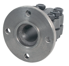
Allpa steel clamp half-coupling with centering ring for marine propeller shaft connections, available for shaft diameters of Ø25, 30, 35, 40, 45 and 60 mm. Features a split clamping hub and a mounting flange with model-specific centering diameter, bolt pitch circle, fixing hole diameter and axial dimensions. Includes 4" and 5" reference flange configurations, Yanmar and Volvo reference versions, and a six-hole configuration for Ø60 mm shafts. Centering diameters range from Ø50 to Ø76.2 mm, while bolt pitch circle diameters range from Ø78 to Ø120.65 mm. Select the correct version according to shaft diameter, centering dimensions, bolt pattern and mating flange compatibility.
- Description
- Ask a Question
-
Allpa Steel Clamp Half-Coupling with Centering Ring for Ø25–60 mm Propeller Shafts
The Allpa Steel Clamp Half-Coupling with Centering Ring is a marine propulsion shaft coupling component manufactured from steel. It combines a split clamping hub, a mounting flange and a centering feature for connection to a corresponding mating flange.
The range includes configurations for propeller shafts with diameters of 25, 30, 35, 40, 45 and 60 mm. Different centering diameters, bolt pitch circles, mounting hole sizes and axial dimensions are available to suit the required coupling arrangement.
The series includes standard 4" and 5" reference configurations, Yanmar and Volvo reference versions, and a six-hole flange configuration for a 60 mm shaft.
Key Features
- Steel construction: Half-couplings manufactured from steel.
- Split clamping hub: Shaft attachment using a clamping arrangement.
- Centering ring: Integrated centering feature for the mating flange connection.
- Flanged connection: Mounting interface with model-specific bolt patterns.
- Available shaft sizes: Ø25, Ø30, Ø35, Ø40, Ø45 and Ø60 mm.
- Multiple centering diameters: Ø50, Ø60, Ø63.5, Ø65 and Ø76.2 mm.
- Multiple bolt pitch circles: Ø78, Ø80, Ø82.5, Ø100, Ø108 and Ø120.65 mm.
- Reference configurations: 4", 5", Yanmar, Volvo and six-hole versions.
- Model-specific dimensions: Different hub lengths, flange diameters, hole diameters and centering geometries.
Technical Specifications
Parameter Specification Brand Allpa Product Type Steel Clamp Half-Coupling with Centering Ring Application Marine Propeller Shaft Coupling Systems Material Steel Shaft Attachment Split Clamping Hub Flange Type Flanged Connection with Centering Ring Propeller Shaft Diameter (D) Ø25–60 mm, Depending on Model Overall Axial Dimension (A) 68–166 mm Axial Dimension (B) 65–166 mm Dimension C -5 to 4 mm, Depending on Model Dimension E 8.5–16.2 mm Centering Diameter (F) Ø50–76.2 mm Flange Diameter (G) Ø100–146 mm Mounting Hole Diameter (H) Ø10.5–17 mm Bolt Pitch Circle Diameter (I) Ø78–120.65 mm Reference Types 4", 5", Yanmar, Volvo, 6-Hole Available Configurations 27
Available Steel Models and Dimensions
The following dimensions correspond to the A, B, C, D, E, F, G, H and I designations in the technical drawing. All dimensions are expressed in millimetres except the reference designation.
Article Shaft Ø D A B C E Center Ø F Flange Ø G Hole Ø H Pitch Ø I Ref. 518007/30 30 68 65 3 11 63.5 127 11.5 108 5" 518045 45 101 98 3 12.5 63.5 132 12 108 5" 518009 25 68 65 3 10.5 63.5 102 10.5 82.5 4" 5180095 30 68 65 3 10.5 63.5 102 10.5 82.5 4" 518011 35 93 90 3 11.5 63.5 127 11.5 108 5" 5180115 35 120 117 3 11.8 63.5 102 10.5 82.5 4" 518012 40 93 90 3 12 63.5 127 11.5 108 5" 5180125 40 120 117 3 11.8 63.5 102 10.5 82.5 4" 518020 60 166 166 -5 16.2 76.2 146 17 120.65 6-Hole 518009Y 25 70 67 3 10.5 50 100 10.5 78 Yanmar 518010Y 30 70 67 3 10.5 50 100 10.5 78 Yanmar 518011Y 35 93 90 3 11.8 65 127 12.5 100 Yanmar 518012Y 40 93 90 3 11.8 65 127 12.5 100 Yanmar 518009V 25 70 70 -3.5 10.5 60 100 10.5 80 Volvo 518010V 30 83.5 83.5 -3.5 10.5 60 100 10.5 80 Volvo 522125 25 85 82 3 8.5 50 100 10.5 78 Yanmar 522130 30 107 105 2 9 50 100 10.5 78 Yanmar 522230 30 107 105 2 9 65 120 10.5 100 Yanmar 522235 35 109 105 4 10 65 120 10.5 100 Yanmar 522240 40 93 90 3 11.8 65 120 10.5 100 Yanmar 522225 25 83 81 2 8.5 63.5 102 10.5 82.5 4" 522330 30 106 104 2 9 63.5 102 10.5 82.5 4" 522335 35 107 105 2 10 63.5 102 10.5 82.5 4" 522435 35 109 105 4 10 63.5 127 11.5 108 5" 522440 40 130 126 4 11 63.5 127 11.5 108 5" 522329 25 83 83 -4 10 60 102 10.5 80 Volvo 522331 30 106 106 -4 11 60 102 10.5 80 Volvo
Steel Clamping Hub
The half-coupling features a split steel clamping hub for attachment to the propeller shaft. Each model has a specified shaft bore diameter and axial dimensions.
Different hub lengths are available for the same shaft diameter. For example, 25 mm shaft configurations include models with dimension A of 68, 70, 83 and 85 mm.
Centering Ring and Flange Alignment
The centering ring is part of the interface between the half-coupling and its corresponding mating flange. The centering diameter is identified as dimension F in the technical drawing.
The available configurations include the following centering diameters:
- Ø50 mm
- Ø60 mm
- Ø63.5 mm
- Ø65 mm
- Ø76.2 mm
The mating flange must have a compatible centering arrangement.
Mounting Flange and Bolt Pattern
The steel half-couplings have different flange configurations, including 4" and 5" reference sizes and Yanmar and Volvo reference versions.
Dimensions G, H and I identify the flange outside diameter, fixing hole diameter and bolt pitch circle diameter, respectively.
The range includes bolt pitch circles of Ø78, Ø80, Ø82.5, Ø100, Ø108 and Ø120.65 mm. The 60 mm shaft model, article 518020, is listed with a six-hole mounting pattern and Ø17 mm fixing holes.
Yanmar and Volvo Reference Versions
Selected half-couplings carry Yanmar or Volvo reference designations. These variants have specific centering diameters, bolt patterns and axial dimensions.
For Yanmar reference configurations, centering diameters include Ø50 and Ø65 mm, while the Volvo reference configurations use a Ø60 mm centering diameter.
The reference designation does not replace dimensional verification of the actual mating flange.
Axial Dimensions and Centering Geometry
The model-specific axial dimensions A, B, C and E must be checked alongside the flange dimensions.
Dimension C includes positive and negative values depending on the configuration. These values are retained as specified in the dimensional data and should be interpreted together with the technical drawing.
Selection and Compatibility
Select the correct Allpa steel clamp half-coupling by checking:
- Shaft Diameter (D): Must match the propeller shaft.
- Centering Diameter (F): Must match the corresponding mating flange.
- Flange Diameter (G): Check the outside flange dimension.
- Fixing Hole Diameter (H): Check the required mounting hole size.
- Bolt Pitch Circle (I): Verify the mounting hole arrangement.
- Axial Dimensions (A, B, C and E): Confirm compatibility with the existing installation.
- Reference Configuration: Check the specified 4", 5", Yanmar, Volvo or six-hole arrangement.
Different half-couplings may share the same shaft diameter and bolt pitch circle while having different axial lengths or centering dimensions. Verify the complete dimensional configuration before ordering.
-
Popular products
-
 1-2 weeks delivery timefrom $ 367.96
-
 1-2 weeks delivery timefrom $ 343.90
-
 1-2 weeks delivery timefrom $ 330.28
-
 1-2 weeks delivery timefrom $ 157.71
-
 1-2 weeks delivery timefrom $ 18
-
 1-2 weeks delivery timefrom $ 328.42
-
 1-2 weeks delivery time$ 398.04
-
 1-2 weeks delivery time$ 980.44
-
 1-2 weeks delivery timefrom $ 157.10
-
 1-2 weeks delivery timefrom $ 10.68