Installing a high-capacity power control device for marine or recreational use requires careful attention. This guide explains how to properly wire a 350-amp rated unit for managing multiple power sources. Correct connections ensure reliable operation and protect your electrical system. Whether upgrading or installing new, following proper steps prevents common errors. Careful setup extends equipment life and maintains steady power. This article offers key tips for a secure and efficient connection. After reading, you’ll confidently manage your system’s power safely.
Introduction to Blue Sea Systems E-Series
Blue Sea Systems E-Series switches provide reliable power control. They are designed for marine and heavy-duty applications. The E-Series ensures safe and efficient battery management. These switches handle high current loads up to 350 amps. Their compact design fits easily in tight spaces. Installation is straightforward, even for beginners. Durable construction protects against corrosion and vibration. Many boaters trust Blue Sea Systems for power safety.

Overview of Blue Sea Battery Switch and Components
The Blue Sea battery switch controls battery connection and isolation. It includes a heavy-duty rotary switch and mounting hardware.
The 350A E-Series battery switch offers robust current handling capabilities.
Terminals are clearly marked for easy wiring. The switch body is corrosion-resistant for long-lasting use. A clear, easy-to-read dial shows switch position. Blue Sea provides detailed installation instructions with each unit. The components fit well with dual battery setups. Proper wiring ensures safe and efficient operation.
What the 350A E-Series Battery Switch Is Designed For
The 350A E-Series switch suits high-current marine systems. It manages power between multiple batteries safely and effectively. This switch is ideal for:
- Dual battery banks on boats
- Isolating batteries during maintenance
- Protecting electrical circuits from overload
- Switching between house and start batteries
- Ensuring reliable power flow under heavy load
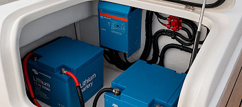
Benefits of Using Blue Sea Systems on Dual Battery Setups
Blue Sea Systems simplify managing dual battery banks. They prevent battery drain by isolating batteries when needed. These switches increase safety and system reliability. Installation reduces risk of accidental short circuits. Key advantages include:
- Easy switching between batteries
- Protects batteries from over-discharge
- Durable build for marine environments
- Clear switch position indicators
- Compatible with various battery types
Understanding the E-Series Battery Switch
The E-Series battery switch is a heavy-duty solution for power control. It handles up to 350 amps for large systems. This switch is designed for reliable manual battery management. The E-Series battery switch offers easy selection between multiple battery banks. It allows users to connect or isolate batteries safely. Its robust build ensures durability in tough environments. The switch is simple to operate, even under load. Overall, it brings peace of mind for power distribution.
Difference Between Selector and Dual Circuit Switches
Selector switches direct power flow from one battery at a time. They are mainly for choosing which battery supplies power. Dual circuit switches handle two battery banks simultaneously.
A Dual Circuit switch provides more flexibility and better redundancy in systems.
Selector switches are simpler but less versatile than dual circuit types. The dual circuit design allows combining batteries for higher power output. Selector switches are often used in single-engine or small setups. Dual circuit switches best fit larger marine and RV needs. Choosing between these depends on the system demands and safety requirements.
How the E-Series Dual Circuit Provides Protection
The E-Series dual circuit switch protects batteries and electronics by isolating faults. It prevents backflow electricity from damaging power sources. Its design reduces risks of electrical shorts and overloads in circuits. The switch ensures safe transfer between battery banks without interruptions. Key protective features include:
- Isolation of battery banks during faults
- Protection against reverse currents
- Prevention of accidental power loss
- High amperage capacity for load safety
- Durable construction for harsh environments
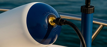
Ignition Protected Features for Marine and RV Use
Ignition protected designs prevent sparks near fuel vapors and flammable materials. This feature is vital for marine and RV safety. E-Series switches meet strict ignition protection standards for safe environments. They reduce fire hazards when installed close to engines or fuel tanks. Important ignition protected features include:
- Spark prevention within the switch
- Compliance with marine safety certifications
- Durable, sealed casing resistant to moisture and dust
- Safe operation under vibration and impact
- Suitable for harsh outdoor conditions
Preparing for Installation
Start by gathering all tools needed for the installation. Ensure the power is off before handling any connections. The E-Series switch must be installed in a dry, accessible location. Check that the battery cables are rated for 350 amps. Plan wire runs carefully to avoid sharp bends or damage. Clean all battery terminals to improve contact quality. Mount the switch firmly to prevent vibration during use. Double-check that all equipment meets your house circuit requirements.
Tools, Fuse, and Circuit Breaker Requirements
| Item | Description |
|---|---|
| Tools | Use insulated wrenches and wire strippers for safe, precise connections on the switch 12v. |
| Fuse | Install a fuse rated slightly above 350 amps to protect the dual circuit plus system properly. |
| Circuit Breaker | Choose a marine-grade breaker suitable for gasoline powered boats to prevent electrical faults. |
| Wire Gauge | Select heavy gauge cables compatible with 350 amp loads and powered boats’ electrical demands. |
| Installation Tips | Always verify polarity and secure connections to avoid shorts in gasoline powered boats. |
Planning Connections for Battery Bank and Alternator
Proper connection planning prevents voltage drops and electrical faults. Connect the positive cable from the alternator to the E-Series switch input. The house circuit and starting battery terminals should connect to the respective outputs. Ensure battery banks are wired in accordance with amperage ratings. Key connection points include:
- Alternator positive to switch input
- House circuit battery to switch output
- Starting battery to the alternate output
- Ground cables securely attached
- Use correct cable sizes for 350 amps
Safety Considerations for 350A High-Amp Systems
High amp systems demand careful attention to safety details. Use insulated tools to avoid accidental shorts during installation. Always disconnect batteries to eliminate shock and arc risks. Check all connections are tight and free of corrosion. Important safety steps include:
- Installing proper fuses or circuit breakers
- Using cables rated for 350 amps minimum
- Avoiding cable contact with moving or hot parts
- Ensuring good ventilation around the battery bank
- Wearing protective gear like gloves and eye protection
Step-by-Step Connection of the 350A Battery Switch
Begin by turning all power off to ensure safety. Mount the 350A E-Series battery switch in a secure, dry spot. Identify the switch terminals for battery and load connections clearly. Connect the positive cable from the battery bank to the correct terminal. Tighten all terminals properly to avoid future loose connections. Attach the on-off control to manage power flow through the switch. Finally, double-check all connections before restoring power. This method ensures a reliable and safe setup every time.
Wiring the Battery Bank to the E-Series Battery Switch
Start wiring by linking each battery bank to its designated switch terminal. Use cables rated for 350 amps to handle the load. Arrange wires neatly to prevent interference or accidental damage.
Ensure proper polarity by matching battery positive to switch inputs carefully.
Secure ground wires separately and check all connections for tightness. Avoid crossing or tangling cables near the on-off switch area. Use heat shrink tubing for added insulation and protection. Label cables to simplify maintenance and troubleshooting later. Proper wiring prevents voltage loss and maintains system efficiency.

Connecting the Alternator and Circuit Battery Distribution Panel
Connect the alternator output directly to the battery switch input terminal. Attach the alternator field wire with an alternator field disconnect switch. Run cables from the battery switch to the circuit battery distribution panel. Ensure all connectors are corrosion-resistant for marine or RV use. Key steps include:
- Connect alternator positive to switch input
- Include alternator field disconnect in the wiring
- Link switch output to battery distribution panel
- Arrange wires minimizing length and resistance
- Inspect all connections for firmness and safety
Using the Battery Selector Switch for Proper Configuration
The battery selector switch lets you manage multiple battery banks efficiently. Use the on-off feature to isolate or combine battery sources. Correctly setting the selector switch optimizes power use and battery life. Always switch off before altering battery connections to avoid sparks. Key tips include:
- Select the appropriate battery bank for your load
- Use “both” mode only when combining batteries
- Avoid switching under heavy load conditions
- Monitor switch condition regularly for wear
- Keep instructions handy for safe operation
Advanced Setup Options
Start with the basic 350A Blue Sea Systems 9003e switch. You can upgrade your system with advanced wiring options. The 9003e allows for seamless switching between house battery banks. This feature is great for marine boat applications needing reliable power. Add a dedicated circuit for accessories like a trolling motor. Use heavy-gauge cables rated for at least 300A in all connections. Consider isolating battery banks to extend battery life efficiently. Proper planning enhances both safety and system flexibility.
Integrating an ACR (Automatic Charging Relay)
An ACR simplifies charging by automatically connecting batteries when charging. The relay senses voltage and links house battery banks as needed.
This integration keeps multiple batteries charged without manual switching.
Connect the ACR between the starting and house batteries for best results. Ensure all cables can handle 300A continuous load safely. The ACR prevents draining the starting battery during heavy trolling motor use. For marine boat setups, it's critical to avoid overcharging any battery bank. Install the ACR near the batteries for efficient voltage sensing. Proper mounting reduces interference and ensures reliable function.
How to Use the Combine Batteries Feature in Emergencies
The combine feature links house battery banks instantly for extra power. Use it only when normal power sources fail or when necessary. This option is vital for emergency trolling motor or marine boat use. Follow these safety steps when combining batteries:
- Turn off all loads before combining
- Confirm switch is in the correct on-off position
- Monitor battery voltage during combined operation
- Avoid long-term use to prevent battery damage
- Switch back to separate mode promptly after emergencies
Configuring Dual Battery and Breaker Protection
Dual battery setups need careful breaker selection and correct wiring. Protect each battery bank with appropriately rated breakers. A 300A breaker is recommended for systems using Blue Sea Systems switches. Place breakers close to the battery terminals for quick disconnect. Regularly inspect breakers and wiring for wear or corrosion. Key setup tips:
- Use a breaker for each house battery bank
- Match breaker rating to cable and load capacity
- Include an on-off switch to isolate batteries safely
- Keep wiring neat and secure from vibration
- Perform routine checks to ensure reliable protection
Maintenance and Troubleshooting
Regular maintenance ensures your Blue Sea Systems E-Series works reliably. Always inspect the main battery connections for corrosion or looseness. Clean terminals and terminals to keep current flow steady and safe. Check switch operation by toggling between positions during engine off time. Inboard gasoline or diesel engines may cause vibration affecting connections. Tighten all bolts and nuts on the E-Series battery switch regularly. Look for signs of overheating like discoloration or melted insulation. Proper attention prevents common electrical failures on marine vessels.
Checking Connections, Fuses, and Breakers for Reliability
Inspect all connections frequently to maintain a safe system. Verify that fuses and breakers match the 350 amp rating of your E-Series switch.
Loose or corroded terminals often cause unexpected power loss or voltage drops.
Use a multimeter to test continuity across the main battery and switch terminals. Review that fuses are intact and breakers haven’t tripped under load. Replace any damaged fuse or breaker immediately with the proper type. Confirm wiring is neat and protected from chafing or saltwater contact. Tighten any terminals that feel loose during your inspection. Preventive checks prolong system life and reduce downtime.
Common Issues with E-Series Battery Switch Installations
Many issues arise from improper wiring or environmental exposure. Incorrect polarity connection is a frequent mistake causing system failure on the E-Series. Other problems include worn cables, corrosion, or loose bolts. Using wrong AWG wiring leads to overheating and voltage drops. Water intrusion sometimes damages switch contacts or the internal mechanism. Battery switches left in “both” position too long may overheat. Here’s a quick checklist to avoid these issues:
- Verify cable polarity before installation
- Use marine-grade AWG cables and connectors rated for 350 amps
- Ensure tight terminal connections on the e series switch
- Protect switch from moisture exposure
- Avoid extended use in combined battery mode
Best Practices for Long-Term Blue Sea Systems Performance
Always use heavy duty cables rated for your system’s amperage. Maintain clean tin-plated copper studs for maximum conductivity and corrosion resistance. Install the battery disconnect switch in a dry, ventilated area. Regularly test the kill switch and battery cables for faults. Keep fuses and breakers properly rated and replace them as needed.
Key best practices include:
- Secure all connections tightly
- Protect cables from abrasion and moisture
- Schedule routine inspections
- Use marine-grade components only
- Document system changes for future reference